- Absorbed laser energy → hot electrons → charge separation at the rear surface → quasi-static sheath → ions accelerated normal to the target (TNSA).
- The cycle-averaged hot-electron density is \(n_{e,0}\approx N_h/(\pi R^2 c\tau_L)\) with \(R=r_L+d\tan\theta\) the rear-side beam radius.
- A Crow/Mora static sheath sets \(E_s\sim E_e/(e\lambda_D)\); Mora’s expanding front and a test ion in the frozen sheath both grow without bound in 1D.
- Without electrons, a charged thin disc (Coulomb / Schreiber) yields a finite \(E_{i,\infty}\) and \(v_i\approx v_{i,\infty}\tanh(\tau_L/(2\tau_0))\).
- Working through Mora vs. test particle, Schreiber, and optimal \(\tau_L\) is Exercise 8.
- Front-side radiation pressure, hole boring, and light sail follow in Lecture 9.
Lecture 7 and Exercise 7 established how collisionless absorption creates hot electrons and sheath fields at both surfaces of an overdense foil. Today we develop the historically dominant rear-side picture — target-normal sheath acceleration (TNSA) — treating the hot-electron population as an input and following the electrostatic expansion into vacuum.
1. From absorption to rear-side acceleration
A fraction \(\eta\) of the laser pulse energy \(E_L\) is converted into kinetic energy of “hot” electrons with representative energy \(E_e\): \[ N_h = \frac{\eta E_L}{E_e}. \] These electrons do not stay confined to the laser–plasma interaction layer: they stream through the foil, heat cold bulk electrons by return currents, and escape at the rear vacuum interface. For foils that are thick compared with the front-side depletion layer (Lecture 9), the sharpest density drop — and often the strongest ion acceleration — occurs at the rear surface.
Two surfaces, one narrative. In PIC you often see sheath fields at both front and rear. Front-side fields are tied to radiation pressure and hole boring; rear-side fields are fed by the hot-electron reservoir. Lecture 8 isolates the rear channel; Lecture 9 returns to the front and closes the circle with light sail.
2. Hot-electron density and the rear sheath
Idealise the rear surface as a step: cold ions remain fixed initially while hot electrons stream into vacuum. Escaping electrons leave a positive surface charge; the resulting potential decelerates them so that many turn around and re-enter. After a short transient, outgoing and returning fluxes balance and the hot-electron density is approximately Boltzmann-distributed in the sheath potential \(\phi\): \[ n_e = n_{e,0}\,\exp\!\left(\frac{e\phi}{E_e}\right). \]
The boundary density follows from placing \(N_h\) electrons over a circular area of radius \(R\) for a duration \(\tau_L\) at speed \(v_e\approx c\): \[ n_{e,0} \approx \frac{N_h}{\pi R^2\, v_e\,\tau_L} \approx \frac{\eta E_L}{E_e\,\pi R^2\, c\,\tau_L}. \] As in Lecture 7 / Exercise 7, \(R\) is the rear-side electron-beam radius \[ R = r_L + d\,\tan\theta, \] not the laser focal spot \(r_L\): electrons diverge while crossing a foil of thickness \(d\).
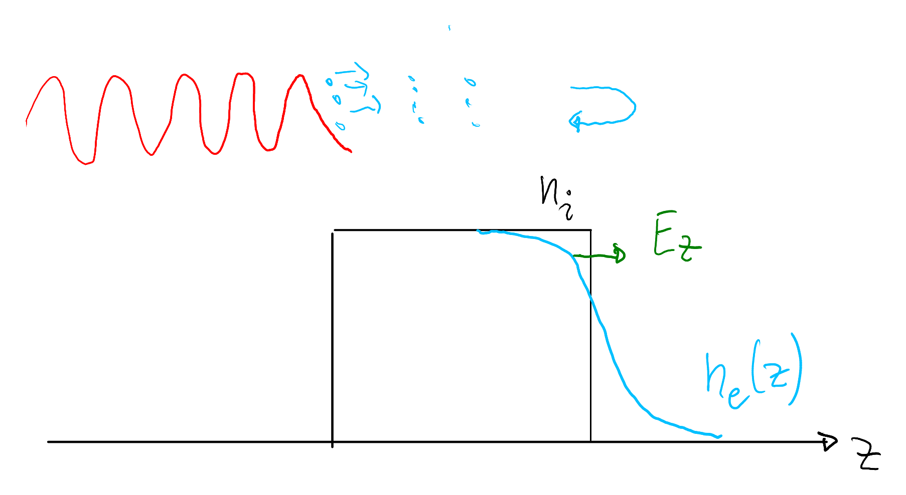
3. Crow/Mora static sheath
With Boltzmann electrons and immobile ions \(n_i=n_{e,0}/Z\) for \(z<0\) and \(n_i=0\) for \(z\ge 0\), Poisson’s equation determines the electrostatic potential. Introduce the Debye length \[ \lambda_D = \sqrt{\frac{\varepsilon_0 E_e}{n_{e,0}e^2}} \] and the normalised variables \(\varphi=e\phi/E_e\), \(\zeta=z/\lambda_D\). Then \[ \frac{d^2\varphi}{d\zeta^2} = \begin{cases} e^{\varphi}-1, & \zeta<0,\\[4pt] e^{\varphi}, & \zeta\ge 0. \end{cases} \] Matching potential and field at \(\zeta=0\) yields \(\varphi(0)=-1\), i.e. \(\phi(0)=-E_e/e\). On the vacuum side one finds \[ \varphi(\zeta) = -2\ln\!\left(1+\frac{\zeta}{\sqrt{2e}}\right)-1, \] and the peak sheath field at the interface is \[ E_s(\zeta=0)=\frac{E_e}{e\lambda_D}\sqrt{\frac{2}{e}}. \]
Order of magnitude. For MeV-scale \(E_e\) and \(n_{e,0}\) of order \(10^{19}\)–\(10^{21}\,\mathrm{cm^{-3}}\), \(\lambda_D\) is sub-micrometre and \(E_s\) can reach TV/m — enough to accelerate protons over micrometres on a picosecond time scale.
Formulating and integrating this Poisson problem in full detail is part of Exercise 8, Question 1; the resulting potential is used as the frozen field for the test-particle comparison in §4.
4. Mora expansion and a test particle in the frozen sheath
Crow et al. and Mora (Plasma expansion into a vacuum, Phys. Rev. Lett. 90 (2003) 185002) studied numerically how the ion front evolves during expansion into vacuum and what maximum velocities can be reached. Mora derived a compact expression for the maximum ion velocity: \[ v_{i} \approx 2c_{s}\ln\left( \tau + \sqrt{1 + \tau^{2}} \right) = 2c_{s}\sinh^{-1}\tau, \] with ion-acoustic speed and normalised time \[ c_{s} = \sqrt{\frac{q_{i}E_{e}}{m_{i}}},\qquad \tau = \frac{\omega_{pi}\,t}{\sqrt{2\exp(1)}},\qquad \omega_{pi} = \sqrt{\frac{n_{e,0}\,q_{i}e^{2}}{m_{i}\varepsilon_{0}}}. \]
As a simple comparison, consider a test ion moving in a fixed sheath potential: assume the Crow/Mora potential of §3 does not evolve in time and ask how much energy an ion starting at \(z=0\) could gain. For charge \(q_{i}e\), \[ E_{k}(\zeta) = q_{i}E_{e}\bigl(\varphi(0)-\varphi(\zeta>0)\bigr) = 2q_{i}E_{e}\ln\left(1+\frac{\zeta}{\sqrt{2\exp(1)}}\right), \] and hence \[ v = 2c_{s}\sqrt{\ln\left(1+\frac{\zeta}{\sqrt{2\exp(1)}}\right)} = \frac{\mathrm{d}z}{\mathrm{d}t} = \frac{c_{s}}{\sqrt{2\exp(1)}}\,\frac{\mathrm{d}\zeta}{\mathrm{d}\tau}. \] With the rearrangement \(\zeta=\zeta_{i}\sqrt{2\exp(1)}\) and the same normalised time \(\tau=t\omega_{pi}/\sqrt{2\exp(1)}\), the trajectory obeys the integral relation \[ \int_{0}^{\zeta_{i}(\tau)} \frac{\mathrm{d}\zeta_{i}}{2\sqrt{\ln(1+\zeta_{i})}} = \tau. \] Figure 8.2 compares Mora’s expansion-front velocity with the numerical solution of this test-particle model. Both expressions grow without bound as \(t\to\infty\), reflecting the idealisations of a 1D (transversely infinite) sheath.
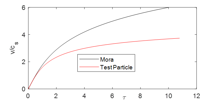
In practice the acceleration is finite: one often truncates it after an effective acceleration time \(t_{a}\) of order the pulse duration (see, e.g., Fuchs, Nat. Phys. 2006). Many works have revisited this expansion scenario; for planar foils, however, the basic descriptions remain largely 1D. Working out the test-particle integral and the comparison plot is Exercise 8, Question 2.
5. Without electrons: charged disc and the Schreiber model
It is therefore natural to consider a slightly more realistic geometry. Suppose the rear-side sheath forms as above, with electrons streaming out, turning around, and streaming back into the target, but only within a finite transverse region of radius \(R\). Figure 8.3 sketches this configuration.
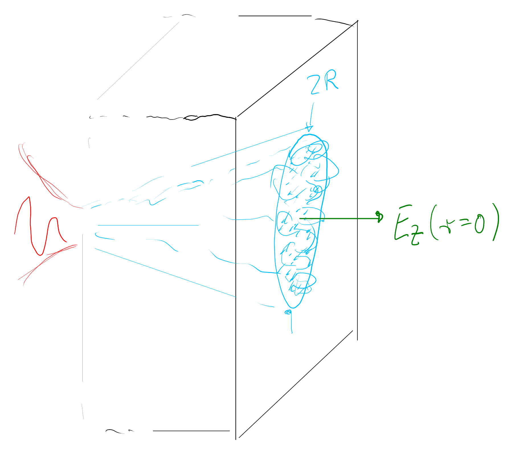
The Poisson equation can still be written and, in principle, solved numerically. A useful first estimate follows by considering only the positive charge and neglecting the electrons: the potential of a uniformly charged thin disc is straightforward on axis, where the acceleration is maximal, \[ \Phi(\mathbf{r}) = \frac{1}{4\pi\varepsilon_{0}} \int\frac{Zen(\mathbf{r}')}{\lvert\mathbf{r}-\mathbf{r}'\rvert}\,\mathrm{d}^{3}\mathbf{r}', \] with constant ion density \(n(\mathbf{r}')=n_{0}\) inside the disc. On axis (\(\mathbf{r}=(0,0,z)\), \(z\ge 0\)) one obtains \[ \begin{aligned} \Phi(z) &= \frac{Zen_{0}}{2\varepsilon_{0}} \int_{-d}^{0}\Bigl[\sqrt{R^{2}+(z-z')^{2}}-(z-z')\Bigr]\mathrm{d}z' \\ &= \frac{Zen_{0}R^{2}}{2\varepsilon_{0}} \int_{\zeta}^{\zeta+\delta} \Bigl[\sqrt{1+{\zeta'}^{2}}-\zeta'\Bigr]\mathrm{d}\zeta', \end{aligned} \] where \(\zeta=z/R\) and \(\delta=d/R\). At the surface \(z=0\), \[ \Phi(0) = \frac{Zen_{0}R^{2}}{4\varepsilon_{0}} \Bigl[ \delta\bigl(\sqrt{1+\delta^{2}}-\delta\bigr) +\tanh^{-1}\!\Bigl(\frac{\delta}{\sqrt{1+\delta^{2}}}\Bigr) \Bigr]. \] As \(z\to\infty\), \(\Phi\to 0\), so an ion of charge \(q_{i}e\) placed at \(z=0\) can gain at most \[ E_{i,\infty}=q_{i}e\,\Phi(0). \]
For a thin disc \(\delta=d/R\ll 1\) this simplifies to \[ \Phi(z) \approx \frac{Zen_{0}Rd}{2\varepsilon_{0}} \bigl[\sqrt{1+\zeta^{2}}-\zeta\bigr], \qquad E_{i,\infty} \approx q_{i}\frac{Ze^{2}n_{0}Rd}{2\varepsilon_{0}}. \] The kinetic energy along the axis is then a function of distance, \[ E_{\mathrm{kin}}(z) = q_{i}e\bigl[\Phi(0)-\Phi(z)\bigr] \approx E_{i,\infty}\bigl[1+\zeta-\sqrt{1+\zeta^{2}}\bigr]. \] Half of the maximum energy is reached at \(\zeta_{1/2}=3/4\), i.e. at \(z=(3/4)R\).
Non-relativistically, the on-axis velocity is \[ v(z) = \sqrt{\frac{2E_{\mathrm{kin}}(z)}{m_{i}}} = v_{i,\infty}\sqrt{1+\zeta-\sqrt{1+\zeta^{2}}}, \qquad v_{i,\infty}=\sqrt{\frac{2E_{i,\infty}}{m_{i}}}. \] Separating variables with \(z=R\zeta\) and introducing \(X=v/v_{i,\infty}=\sqrt{E_{\mathrm{kin}}/E_{i,\infty}}\) together with the ballistic time \(\tau_{0}=R/v_{i,\infty}\) yields Schreiber’s relation (PRL 2006) \[ \frac{t}{\tau_{0}} = X\left(1+\frac12\frac{1}{1-X^{2}}\right) +\frac12\,\tanh^{-1}X. \] In particular, half of \(E_{i,\infty}\) is reached at \(X=1/\sqrt{2}\) after \(t_{1/2}\approx 1.85\,\tau_{0}\).
Finite energy even for infinite time. Unlike the 1D Crow/Mora sheath, the 3D disc potential falls off at large \(z\), so \(E_{i,\infty}\) remains finite even if acceleration lasts forever. In laser–plasma experiments one still truncates at an effective time \(t_{a}\) of order the pulse duration (fields are maintained while the laser feeds hot electrons). Both Fuchs (Mora-based) and Schreiber (Coulomb disc) describe observed TNSA proton energies acceptably well; the finite \(E_{i,\infty}\) of the disc picture has the intriguing consequence of an optimum pulse duration at fixed laser energy (Exercise 8, Questions 3–4).
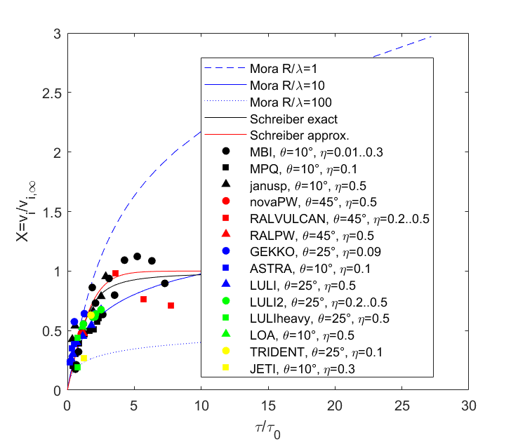
When \(E_{i,\infty}\) approaches the ion rest energy one should solve the relativistic equation of motion; a closed analytic form is not available, but approximate solutions are discussed in Schreiber et al., HPLSE 2014. For the non-relativistic Schreiber law, a Taylor expansion in \(X\) shows that the \(\tanh^{-1}X\) term dominates, motivating the compact approximation \[ v_{i} \approx v_{i,\infty}\,\tanh\!\left(\frac{\tau_{L}}{2\tau_{0}}\right). \] Figure 8.4 compares the exact and approximate Schreiber models with Mora for several \(R/\lambda\), including experimental data as in Schreiber et al. (2006). Relating the Mora and Schreiber scales requires a choice of \(R/\lambda\) (through \(n_{e,0}\) and \(E_{e}\) vs. \(E_{\infty}\)); that comparison is the core of Exercise 8, Question 3. Identifying \(E_{\infty}\) with absorbed laser power, \[ E_{\infty} = mc^{2}\sqrt{\frac{2\eta P_{L}}{P_{R}}}, \qquad P_{R}=\frac{4\pi\varepsilon_{0}m^{2}c^{5}}{e^{2}}\approx 8.71\,\mathrm{GW}, \] then leads to the optimal-\(\tau_{L}\) problem of Question 4.
6. Outlook
TNSA explains why absorption and hot electrons matter for ion beams from thick foils. The 1D Mora picture and the 3D charged-disc (Schreiber) picture give complementary limits: unbounded expansion vs. a finite Coulomb energy. Real experiments also show front-side acceleration when radiation pressure displaces electrons into a depletion layer and the reflecting surface bores into the target — or, for foils as thin as that layer, when the whole slab rides as a light sail.
Lecture 9 develops that front-side story with PIC (linear → circular polarisation), hole boring, and the return to light-sail acceleration from Lecture 2.